By Train from SAC
Revisit of my NVDLA adaption project in Novumind
Introduction to NVDLA
The NVIDIA Deep Learning Accelerator (NVDLA) is an open-source hardware project designed to accelerate deep learning inference tasks. Its flexible, scalable architecture enables developers to implement AI acceleration on various platforms, from FPGAs to ASICs. By offering a complete stack of hardware and software, NVDLA has become a cornerstone for many projects in the AI hardware space, making it an invaluable tool for prototyping and development.
Project Motivation
At NovuMind, a company focused on developing innovative convolutional chips for AI applications, we sought to benchmark our hardware against existing solutions like NVDLA. However, NovuMind’s architecture differed significantly: it lacked a traditional CPU or microcontroller, relying instead on Kernel Mode Driver (KMD) control for direct register management. To ensure a fair comparison, we adapted NVDLA to operate under similar conditions, eliminating its CPU and microcontroller to align with our unique architecture. This effort was crucial for demonstrating our chip’s performance in a controlled, apples-to-apples manner.
Technical Approach
The project’s technical focus was on modifying the NVDLA architecture to remove the embedded CPU and microcontroller and shift all register control responsibilities to the KMD. Here’s how we achieved this:
- Removing Embedded Controllers: We stripped the CPU and microcontroller from the NVDLA’s design, leaving a bare-bones configuration that required external control.
- Building Layer-Specific Register Controllers: We implemented custom KMD logic to handle direct register read/write operations for each neural network layer, such as convolution and pooling. This ensured precise management of data flow and operations.
- Integrating with Existing Tools: We adapted the compiler provided by NVDLA to generate configurations compatible with our KMD-driven approach. This involved modifying the software stack to streamline the translation of high-level neural network models into hardware instructions.
Challenges and Solutions
Adapting NVDLA to this new architecture posed several challenges:
- Compatibility with the Existing Compiler: NVDLA’s compiler was originally designed to work with its embedded CPU. We re-engineered parts of the compiler to align with our KMD-driven architecture, ensuring a smooth integration.
- Complex Register Management: Managing registers for multiple layers directly from the KMD was intricate. We resolved this by designing modular, layer-specific logic within the KMD to simplify control and reduce errors.
- Validation Without Native Simulation: Since NovuMind’s chip lacked native support for NVDLA’s simulation tools, we relied heavily on direct hardware testing and adjustments to ensure correctness.
Validation with Caffe
To validate our modifications, we used Caffe, a popular deep learning framework, to run neural network models on the adapted NVDLA. We focused on benchmarking tasks such as image recognition and convolution-heavy operations, analyzing performance metrics like throughput and latency. By successfully running these models, we confirmed the functionality and accuracy of our custom KMD-driven implementation.
Results and Implications
The project achieved its goal of enabling a direct comparison between NovuMind’s convolutional chip and NVDLA. Key outcomes included:
- Performance Insights: The adapted NVDLA provided critical data on throughput and power efficiency, highlighting the strengths of our architecture in convolution-heavy workloads.
- Scalable Design: The modifications demonstrated the flexibility of NVDLA’s open-source design, showing its potential for adaptation to unique hardware environments.
- Future Applications: This project laid the groundwork for further innovations in AI hardware, illustrating how open-source accelerators can be customized for diverse architectures.
Conclusion
Adapting NVDLA for direct KMD control was a challenging but rewarding experience. It underscored the versatility of open-source hardware and its potential for fostering innovation in AI. At NovuMind, this project not only validated our chip’s performance but also provided valuable lessons in hardware-software co-design. As AI hardware continues to evolve, such projects will remain essential for pushing the boundaries of what’s possible.
Losing target
When started to write blogs my plan was to prepare & practice for posting more important staff in the next year or two to somewhere with higher influence, to prepare for stronger background for O1 visa..
But luckily my O1 visa application got approved earlier this year, and I don’t have anything I need to do to improve my writing skills.. So kind of losing the target.
I have wrote a lot of random things saved as “draft” on this blog..
Later I will rethink what I could share, maybe small projects or some state-of-art learning topics, also consider of continuing the previous step-by-step deep dive.
Don’t want to work
Don’t want to rest
Don’t want to game
Don’t want to think
Don’t want to talk
Don’t want to do anything
3 Weeks before finishing the MSEM degree
as title. relief
Update 10/19: 1 week left
Everything done
Recovering from surgery
As titled.
Getting better recently. Consider to continue adding more posts in the near future 🙂
Personal Software Configuration
Code Editor: Sublime
C++ compiler on Windows: MSVC(Visual Studio) on Windows Terminal
Doc/Slides Editor: Google Docs
Video Recorder/Streamer: OBS Studio
Chat & Social: Discord, Skype
Virtual Machine Software: Virtual Box
Recommend Open Source & Free Edit Software:
Picture Editor: Gimp(for jpeg, NO recommend to build from source),
Raw Picture Editor: Darktable (for Raw)
Audio Editor: LMMS
[TTTA] Episode 2 Hello Color Triangle

Hope you get all the points from the first episode!
If you are familiar with the real DX12 Hello Triangle sample, you might have noticed that the sample I created in episode 1 was incomplete. In this episode, we’ll delve into the full “Hello Triangle” sample and explore some new concepts to understand how to draw this more complete version.
Screenshots of this new sample will be included in this blog, but feel free to download latest version of Intel GPA and open S2-HelloColorTriangle.

From the result, we can find that the triangle is colorful, and background has been painted to blue. Also, the number of API log has been changed from 1 to 4, adding 3 new calls.
In this blog series, we’ll discuss “ResourceBarrier” in detail in a future episode. For now, it’s important to understand that a ResourceBarrier in DirectX 12 is used to synchronize resource states between different GPU operations. It ensures that resources are not read or written in an inappropriate state, which is critical for correct rendering and performance optimization. Think of it as a traffic controller that manages how different parts of the GPU access memory resources.
Let’s start with “ClearRenderTargetView“.
ClearRenderTargetView is a function from DX12 command list. Here from GPA we can easily observe what parameters this function need.
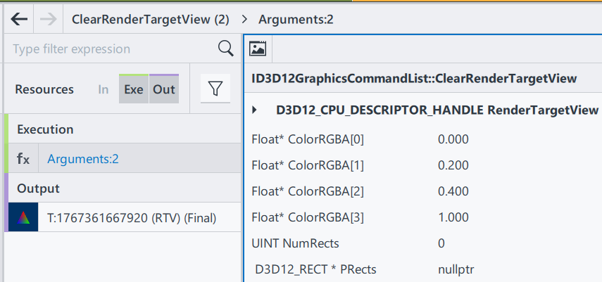
RenderTargetView: Represent the start of the heap to be cleaned
ColorRGBA[4]: a vector of float to represent a color
NumRect/PRects: The target vector of D3D12_RECT objects to be cleaned
If PRects is NULL, ClearRenderTargetView clears the entire resource view instead.
The purpose of this function to fill the entire render target with a single color. This is often used at the beginning of a new frame to clear the remnants of the previous frame’s rendering. Here, by having nullptr in PRects, we are setting up the entire frame to color [0, 0.2, 0.4, 1], a mixed color of blue and green. Since ClearRenderTargetView is before “DrawInstanced”, the cleared color becomes a background automatically.
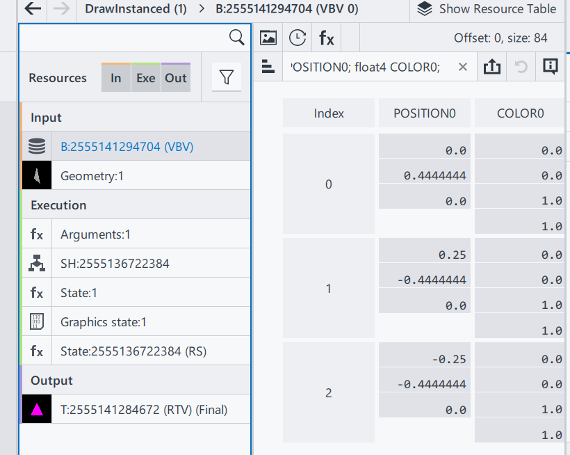
Then, let’s go to the next section, DrawInstanced. It keeps almost everything the same as the one introduced in episode 1.

Shader Source Code(SH): Same as E1
Pipeline State/Non pipeline state: Same as E1
The only difference is the input vertices buffer.

Position0: Same as E1
Color0: In this example, 3 vertices of the triangle now has different color. Since color values are stored as the order of RGBA, we can tell that:
Index0: top middle (0, 0.44, 0), is red(1, 0, 0)
Index1: bottom left (0.25, -0.44, 0), is blue(0, 1, 0)
Index2: bottom right (-0.25, -0.44, 0), is green(0, 0, 1)
Thus, when we are drawing this triangle on the screen, we are drawing 3 vertices with different color. A question just comes to us: what will happen to the pixels that are in the middle? To well understand this, we will introduce one of the most important terms in computer graphics – Rasterization.
In a word, rasterization is responsible for converting geometry/vector images into pixel information. In our case, the geometry we input is the triangle. We input position and color information of 3 vertices here as a geometry of a triangle, and as for output we will get a set of all pixels that we find belong to the geometry shape, including each pixel’s position and color.
Rasterization process involves combinations of algorithms, and as a series focusing on communications between applications and GPUs, I am not planning to introduce all the math details here in this episode. For now, let’s only remember that a rasterization process can find all necessary pixels through a complex edge determination process, and interpolate all pixels’ color using the given colors.
Then let’s get back to the original question: Why having vertices of 3 different color will give us different colors in different position?
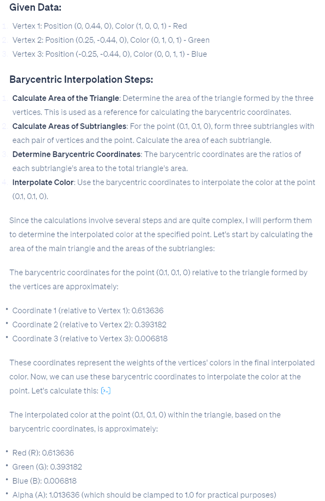
This is because of the algorithm we use in interpolation is Linear interpolation. specifically barycentric interpolation in modern 3D APIs. This method calculates the contribution of each vertex to the target point. For example, if a point is closer to a red vertex, the output will be more red. Each pixel has different distances to the three vertices, resulting in varied colors.
On the right is the process from ChatGPT, on calculating interpolation color value on pixel position (0.1, 0.1,0) in our case.
After calculation, we find the color in that area should be around (0.61,0.39,0,1).
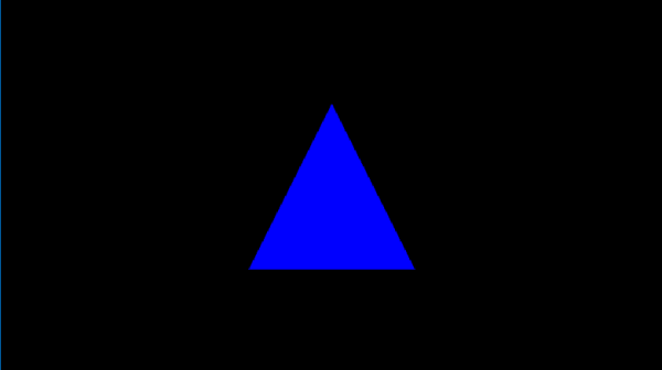
In a graphics pipeline, before getting the final rendering result, there is another step calculating the pixel shader; however in pixel shader we just pass through the value to be the final result.
Here, let’s have a quick peek of the final result in the beginning. The white dot in the middle is (0,0,0,1). Thus, (0.1, 0.1, 0) is on the top right of the white dot, in Quadrant I. We can see that the color is between red and green, and more red; which indicates that our calculation result is correct.
This concludes this episode. I hope it gives you a better understanding of this colorful triangle. Rasterization is a significant topic in computer graphics, but grasping the concept and scope of rasterization is more important than understanding the underlying mathematics. In later episodes, we will continue this learning journey, exploring increasingly complex samples and introducing more concepts step by step.
December Travel & First Camera Experience

Flight: Sacramento – Las Vegas, Dec 13th; Las Vegas – Sacramento, Dec 17th
Rout:
Day1: Las Vegas Airport – Bellagio Hotel – Hell’s Kitchen – High Roller
Day2: Bellagio – Zion National Park(Night sky) – Page Town
Day3: Page Town – Upper Antelope Canyon – Lower Antelope Canyon – Horseshoe Bend – Lake Powell night sky
Day4: Page Town – The Grand Canyon – Kingman
Day5: Kingman – Hoover Dam – LAS Chinatown -The Sphere(Postcard from Earth) – Archery training
Some photos:


Hello World!
Welcome to WordPress! This is your first post. Edit or delete it to take the first step in your blogging journey.
[TTTA] Episode 1 Hello Triangle
In the first episode, let’s talk about drawing a single triangle on your screen. By analyzing a frame captured from a triangle application, let’s learn what need to offer to the operating system to render this blue triangleIn our inaugural episode, we’ll explore how to render a single triangle on your screen. By examining a frame captured from a simple triangle-rendering application, we’ll learn about the essentials provided to the operating system to achieve this.
Begin by downloading “S1-HelloTriangle.zip” from the shared drive and extract its contents. Open the frame using the “Frame Analyzer” to proceed.

You’ll notice the blue triangle in the center—the outcome of our rendering. On the left, the API log lists just one item, signifying that a single “DrawInstanced” API call was responsible for rendering our triangle on the screen.
By selecting this draw call, a new “Resource” window appears, showcasing three categories: Input(In), Execution(Exe), and Output(Out). These resources are crucial for understanding the data required for rendering.

We will through those resources one by one to find out what has been used in this rendering.
Starting with the Input section, we find two items. ‘B:’ denotes a buffer, followed by a unique SHA code. The term ‘VBV’ (Vertex Buffer Views) indicates that this buffer stores the vertices.
This particular buffer contains a trio of vectors, each comprising two components: Position and Color.
Position: A trio of float vectors, each within the range of [-1.0, 1.0], designating the x, y, and z coordinates. For our 2D example, all z-values are zero, with the x/y pairs forming a triangle onscreen.
Color: A quartet of float vectors, ranging from [0.0, 1.0], representing the ‘RGBA’ color values where, in our case, we have full blue with complete opacity.
Why do colors define in floating points? While designing the interface, ideally an application doesn’t need to know what hardware it needs to be executed. Thus, when rendered in an 8-bit rendering system, the result color will be in range [0, 255]; on a 10-bit rendering system (Also named HDR10), it means the final range will be in [0, 1023].
Why colors and transparencies are defined on the vertices instead of the surface/triangle? In a modern rendering system, a surface is always represented by 3 vertices, and in general the number of surfaces will be larger than the number of vertices. In this case, defining color and transparency information on vertices can reduce the amount of parameter savings. The color and transparency values of a vertex are reused for all surfaces that share that vertex.
Geometry Input: A visual result of the input vertices, drawing a triangle in a 3D space.
That’s the end of Input section.
In execution section, to simplify this episode, we are only focusing on Arguments and Shader(SH):
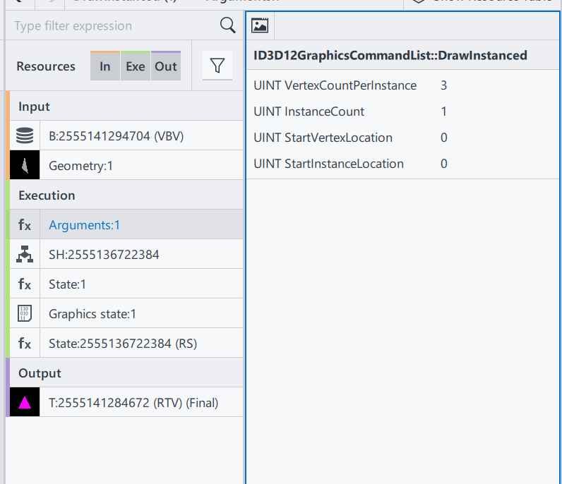
ID3D12GraphicsCommandList::DrawInstanced: This is the draw command used in this rendering process. Definitions can be found here. ID3D12GraphicsCommandList::DrawInstanced
VertexCountPerInstance: Number of indices read from the index buffer for each instance.
InstanceCount: How many instances/surfaces are there in this draw call. Here we only have 1 triangles.
StartVertexLocation: Sometimes the vertex buffer saves additional information for other draw calls. Here offer an offset to find the correct vertex
StartInstanceLocation: A value added to each index before reading per-instance data from a vertex buffer.
From the DrawInstanced command’s arguments, we ascertain the intention to draw a single instance represented by three vertices.

Shader codes of this rendering system, as a programmable input to define how to render a result.
SH: 2555136722384 Shader resource, with its HASH
HLSL(High-Level Shader Language): A shader language developed by Microsoft
VSMain: The main function of Vertex Shader
PSMain: The main function of Pixel Shader. This will be the final value of a Pixel
The full design and execution of the shader system is complicated, and will be gradually extended in this series, when the demo is getting more complex. To check the full DX12 pipeline system Pipelines and Shaders with DX12.
And that wraps up the Execution section! We’ll touch upon the Output results when relevant in future discussions.
To recap, we’ve covered:
- Input: Vertex positions and color data.
- Shader: Source code specifying VSMain and PSMain functions.
With these inputs prepared, we’re set to execute the “DrawInstanced” command:
DrawIndexedInstanced(3, 1, 0, 0, 0)
Executing this function draws the blue triangle on the screen, achieving our rendering goal.
Thank you for joining Episode 1! Your thoughts and questions are welcome in the comments below. Stay tuned for the next installment!
